Modeling Actions
Revision as of 19:46, 30 January 2018 by Rsalter (talk | contribs) (→Add a Component, Display or Control)
This section summarizes all of the commands and gestures used to build a model in the Design Frame.
Creating and Naming a New Project
- Click File | New in the Menu. This will create a new project with an untitled main capsule
- Enter the Capsule's name in the 'Model Name' text area.
- Save the project using File | Save As
Add a Component, Display or Control
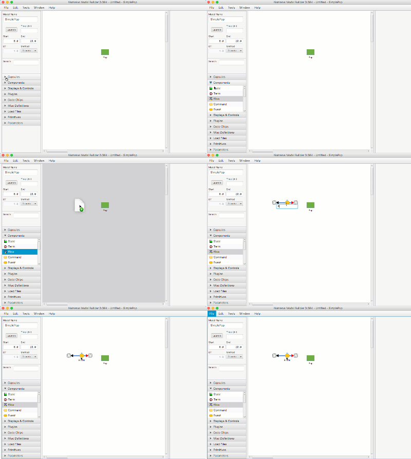
- Open the Components (or Displays & Controls) design tab.
- Select the component by pressing on the mouse.
- Drag the component to the Model Canvas.
- Name the component (or hit return; you can rename it later).
Programming a Component
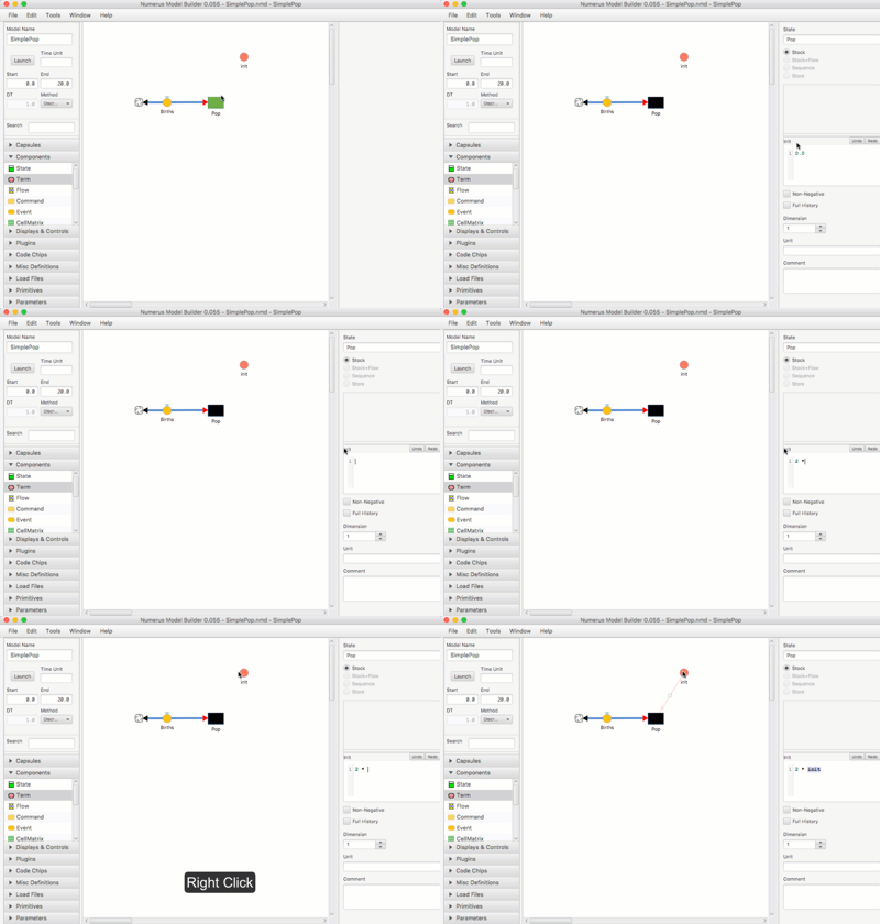 Each component type is associated with a Property Pane which appears when you select the component. If a component requires an equation or program the Property Pane will contain a Value text area. You can type into this text area to specify the equation or program. You can also right-click any component to include that component's name in the code.
- Select the component by left-clicking
- If necessary, you can click the label Value to select all of the text in the text area for deletion.
- Enter the program into the Value text area.
- Right-click any component to insert its name into the Value text area at the cursor.
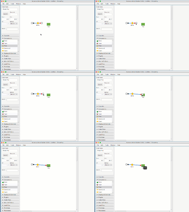
Connect Flow to Stock
- Drag the cloud from the Flow connector over the Stock.
- You can delete the connection using the Flow property pane.
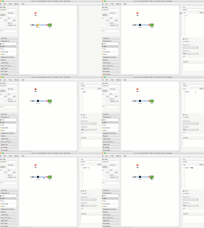
Connect Term and Stock to Flow By Programming
- Click on Flow to reveal its Properties Pane
- Click on the 'Value' label to select all of the text in the Program Text Area.
- Right-click on Term -- its name will appear at the cursor in the Flow Program Text Area (or type the name at the cursor). A connector from Term to Flow will appear.
- Continue by right-clicking (or typing) to insert Stock name into Text Area and create connector from Stock to Flow
Creating Dependency Connections
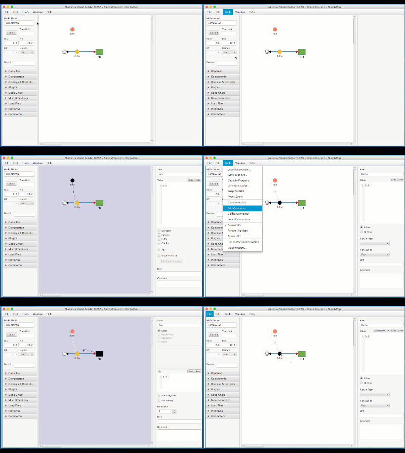
A dependency connection asserts that one component must use the value of another in its equation. Dependency connectors remain dashed until the equation makes use of the dependency ("fulfilled"). A simulation will not launch until all dependencies are fulfilled.
- Select Tools | Add Connector
- Click on the source of the connector. A dashed band between the source and mouse appears.
- Click on the target of the connector. The connector will appear.
- Dependency connectors may be similarly selected for deletion using Tools | Delete Connector.
