Numerus WebKit
Numerus WebKit (NWK) is a technology for building powerful simulations that run in a Web browser. It consists of applications and APIs that support the design of models along the lines of NetLogo (NL), but using conventional languages such as Java, JavaScript (JS) and Python.[1] These applications are deployed either from a remote server, such as Amazon Web Services (AWS) Elastic Beanstalk (AWSEB), (or, in Java mode, any other server that supports WebSockets, or in JS mode, from any conventional Web or Cloud server); alternatively, they can be run locally without using any network connectivity using a localhost server. JS development only requires text editing, and Java development can take advantage of the Eclipse J2EE (Jakarta) platform using the Apache Tomcat server.
This document describes the NWK architecture, APIs and applications. Tutorials, documents describing example models, and a complete user manual, are forthcoming.
NWK Concepts
A simulation program is a system that maintains a global state that evolves over time. A simulation is starts in some initial state, and incurs state changes following successive strobes from an external source (which we call the clock). The state may consist of a single data value or multiple data values mapped out over the internal structure of the simulation. An example of the former is a simple simulation of exponential growth, where the current population is the only value of interest. The latter is exemplified by a spatial or agent based model where simulation state is distributed over individual agents or cells. At each time step the state change algorithm determines the new state from the current and possibly past states of the system. As the simulation runs, the user is presented with displays that illustrate the simulation's state. Time in a simulation is measured in clock ticks which may be mapped to model-time values. A simulation may run for a fixed interval, or may operate in an unbounded time frame.
A spatial simulation models a domain of cells or network nodes organized topologically as a tesselation of 2- or 3-dimensional space, in a Cartesian, or, possibly, hexagonal lattice. Cells have a fixed location and one intrinsically allocated state value, a real number which is associated with a color.
In an agent-, or individual-based model, agents exist in the space defined by the spatial topology and are mobile. In addition to location, their intrinsic state values include color and size. Optionally, speed and direction ("theta"[2]) values can be assigned that direct movement. We use the term SimWorld to refer to the combined cell/agent universe.
The NWK platform uses a Web browser to create a presentation of the simulation to the user. The presentation is separate from the model logic that determines the state evolution of the program, even when both are running on the client. When client and server are both used to execute a simulation, a WebSocket facilitates communication between the presentation and model logic. Consequently, the user must first connect the presentation to the model logic. This step is maintained even for client-side-only deployment, for the sake of uniformity. Disconnecting and reconnecting is a simple and reliable way of restarting a session.
To assist with model creation NWK provides a Project Manager application. Using this, the programmer creates a Project blueprint, essentially a file containing the Project DNA, stored separately from the project directories. The Project Manager reads this file and first parses the JSON contained in the blueprint to weed out any errors. Once a blueprint is correct, the Project Manager creates directory structures for the project, adds the project DNA file constructed from the blueprint, and inserts runnable but empty Java or JS source files for the model logic. As the project develops, changes may be made to the actual project DNA to fine tune the application. The Project Manager also has a function for retrieving deployed Project DNA files and correcting the blueprint, so that using the workflow recommended in a later section, the blueprint will always be current.
We next explore simulation programs from the point of view of the user, and then discuss how these programs are organized architecturally and in terms of their model logic.
User Experience

This image shows the browser window running the sample agent-based application "Rock Paper Scissors", with the following features:
- Model Inputs
- These sliders set parameters for the simulation. Changes are forwarded even while the simulation is running and my have immediate effect.
- Timers
- These windows show the current model time. The left window counts up from 0. If the simulation is designed to run for a fixed time period, the right timer window will be initialized to that time and will count down.
- Operating Buttons
- The Connect/Disconnect buttons activate/deactivate the WebSocket, with the Connect button initializing the application. (Note that this functionality is maintained in the JS platform for the sake of uniformity.) Disconnecting and Connecting is one way to restart the application; reloading the page is another.
- The Reset, Step and Start/Stop buttons operate the simulation. Step executes a single time step, Start/Stop bring about continuous operation, and Reset restores the initial state and resets the timers. Double-clicking Reset also reinitializes the application.
- Speed Control
- This determines the real-time interval between steps.
- Displays
- A spatial or agent-based simulation will include a "SimWorld" display that uses graphic cues to show the current state of the model. Among these cues are location and color, for both cells and agents, and, additionally, size and shape for agents.
- Other displays such as Spys (showing a single current value) graphs, tables, etc. are specified in the Project file (see below).
- Side Panel
- The browser presentation has a side panel which can be shown and removed as needed. Currently this side panel contains model documentation and a log window for WebSocket status reports. A dashboard for altering some properties of the displays, such as the dimensions of the SimWorld, is forthcoming.
System Architecture

NWK architecture revolves around 5 major structures. Refer to the diagram on the right to understand the organization of these items.
- Project
- The Project (or Project "DNA"), is a JSON[3] object contained in a text file, specifying the parameters that configure the elements of both the simulation and the presentation. Details will be given below. If the Project Manager is used to initialize a a project, the programmer first creates a blueprint, essentially the Project DNA file in a separate directory. As mentioned above, the Project Manager uses the blueprint to create a new runnable (but semantically empty) project.
- Presentation
- The Presentation supports visualization and user inputs in the browser. This structure is usually constructed directly in the Presentation API from the data contained in the Project JSON object. All elements of the project pertaining to the visualization and input portal required by the project. These include the agent/cell display (the "SimWorld" display), graphs, tables, etc. Specifications for this aspect are almost always covered by the contents of the Project file and require no attention from the model programmer.[4]
- Simulator
- The Simulation structure, which contains the "business logic" for the model. This consists of 2 parts: the simulation API, which defines the data structures and methods used in the model, and the model itself. The simulation API supports the "turtle/patch" abstraction for agent-based models (ABMs), familiar from NL, but contains some additional capabilities, such as a network basis that substitutes for the patch abstraction, and support for system dynamics models using stocks and flows that can integrate with the ABMs. The simulation API is also configured directly by the Project DNA structure. Model designers can focus entirely on the model structure. One crucial property that we will insist be maintained is that changes to all parts of state occur simultaneously. In other words, any algorithm used to determine one part of a new state only relies on the current or past state of itself and any other part of the state, so that the order in which different parts of the state are computed is immaterial to the outcome.
- Clock
- Clock refers to an external module that provides signals or strobes to the simulation for it to update its state. The clock is controlled from the user console in the browser and can be programmed so that the interval between strobes represents a particular interval of model time (called dt).
- Dispatcher
- This unit facilitates communication between presentation and simulation elements of the application. When a project is loaded into the browser and communication is established, the dispatcher initializes a new simulator with its required parameters. The dispatcher communicates control signals from the presentation to operate the simulator, and any parameter changes that result from user gestures on sliders, switches or other input components. In response, the simulator uses the dispatcher to forward data (called a status report) to the presentation that it needs to update its visual elements.
Architecture in Client/Server and Client/Client Modes
Depending upon the language chosen for programming the model, this architecture is mapped out either across the client and server platforms, or is contained entirely in the client.
Java Platform

Since Java is not native to the browser, programming the model in Java requires server-side support. We use WebSockets to facilitate communication between server and client. The illustration shows the dispatcher divided into two asynchronous units operating separately with the simulator and the presentation. The WebSocket[5] is a robust protocol that manages communication with significant fault tolerance. This robustness translates to a highly robust execution environment for the final application.
The preceding remarks also apply to Python or other model logic coding using an appropriate server. Our experience with Java makes use of the Apache Tomcat server and the Eclipse J2EE design platform. Deploying Tomcat applications is particularly easy: the code is archived in a ".war" file and dropped into a Tomcat "webapp" directory (or, in the case of Elastic Beanstalk, uploaded to the server). Subsequent updates simply overwrite the archive. However, an external server is not needed if one installs a local Tomcat server on their computer.
JavaScript Platform

The JavaScript platform requires no special server features inasmuch as the entire application is downloaded and run in the client. In this case we maintain the same communication regimen but replace the WebSocket with a local function callback protocol. Consequently the client/server and client/client configurations offer identical structures, which facilitates Numerus' obligation for program maintenance of these platforms. Similarly, activating a local server obviates the need for an external delivery method.
Model Organization
We now provide a summary of the model algorithm for agent-based projects using the Java platform (the JS platform follows the same pattern). The code uses NetLogo terminology turtle and patch, respectively, in the class names used for agent and cell base and derived classes. A main class given the name specified in the Project blueprint, oversees simulation operation. These 3 classes respectively extend NLTurtle, NLPatch and NLSimMain. Each turtle or patch object corresponds to a single agent or cell in the model. The main class has data structures turtles and patches to hold all of these objects. Initializing the simulation causes these data structures to be filled according to the Project DNA.
Simulation Cycle
In spatial and agent-based systems, turtle and patch individuals maintain local state. During a clock cycle these object compute their next state. Usually each cycle requires one or two visits to some set of turtles and/or patches, possibly all of them, asking each to compute its next state. This is generally the most computationally intensive part of the cycle. But with efficient design, there are ways to minimize the number of individuals that must be visited, knowing that their states will not change. The base classes have ways to distinguish and control which individuals the cycle must visit, thus greatly improving performance.
Each clock step of the simulation is subdivided as follows:
- Step
- The next state is computed by the following operations:
- Coordinate
- The main program performs any preliminary action on global data, or on the turtle or patch collections.
- Visit
- Individual patches and turtles compute their next local state.
- Shift
- The next state becomes the current state, and the clock is advanced.
- Visit
- Shifting may require a second visit pass.
- Update
- Any required cleanup is performed. State data is sent to the browser.
Stores
States are represented using the Store class, a generic class which can hold any data type. Newly computed states are assigned to the store's next property. If a store is registered with the main program, the main program will perform the shift from next to current during the Shift cycle. Turtles and patches have registered stores for properties such as color, size, location, speed, and direction. Additional application-specific stores can be declared and registered. If shifting the store value from next to current is all is required, (and it usually is), a second visit during the shift cycle can be avoided.
Stocks
A special type of store, called a Stock, is used in system dynamics (SD) settings to model continuous functions. NWK stocks operate like those in well-known system dynamics modeling platforms, such as Stella, Vensim and Berkeley Madonna, using RK4 integration to maintain accuracy. Stocks may be used in a purely SD model, or may be part of the environment modeled in a spatial or agent-based model.
VisitMode
Control of the visit schedule is specified with the VisitMode parameter, in particular the order in which visits to turtles and stocks occurs. As an exception that proves the rule, it may be advantageous to visit turtles before patches, or patches before turtles, and use the newly computed next values in, say, patches when computing the next state of the turtles, or visa versa. The VisitMode values currently supported are:
- A_C: turtles before patches
- C_A: patches before turtles
- A: turtles only
- C: patches only
- No: no visits
- SD: system dynamics using Euler method integration (no visits)
- SDRK4: system dynamics using Runge-Kutta[6] 4 integration (no visits).
Additional VisitModes may be added as this platform develops.
Directory Structures
Java Platform


The picture shows the directory structure used by the Java platform, created as a dynamic web project for deployment on Tomcat, by EclipseEE. The project name (WX) acts as a group id for a set of related simulation applications. Each application specifies a name in its Project DNA. These directories are constructed by the Project Manager app using the Project blueprint file, and the code templates generated during project initialization use the name to prefix the names of the Java and JS model logic classes. The model logic code for each application is thus contained in the java directory subdirectory corresponding to that name. The classes created by the Project Manager are generally sufficient for models with a level of complexity comparable to NetLogo, and in any case serve as the root of the computational environment. The opportunity exists, however, to create more complex simulations by extending the code base with additional classes and/or dependencies.
Similarly named subdirectories of webapp each contain the HTML code for the application and have the identical structure shown below.
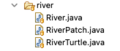
Java Model Code Directory
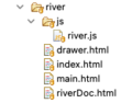
Java HTML and Presentation Directories
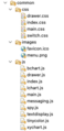
Java Presentation and Dispatch Structures


These images respectively show the contents of the model code directory (subdirectory of java) and the HTML/presentation directories (subdirectory of webapp).
Three of the HTML files are automatically generated by the Project Manager app from data contained in the Project blueprint file, using the project name as prefix. These files constitute the HTML loaded into the browser. The fourth (riverDoc.html) was added and appears in the documentation window of the side panel.
The js subdirectory contains the Project DNA file itself (i.e., river.js). These files are generally complete when deployed.
The right-most image shows the JavaScript, CSS and image files used to implement the Presentation and Dispatch elements of the application, as subdirectories of the common directory. Most of the heavy lifting is done by main.js, which contains the drivers for the dispatcher, input and visualization components. Code for particular components (e.g., lchart.js for linechart, etc.) are contained in their respective files. Consequently, new "widgets" in later releases are easily added to the API.
JavaScript Platform

The JavaScript platform is simpler since it does not have a java directory. The common directory is extended to include the JS model API, along with the same files used for Java Presentation support, with a small change to substitute callbacks for WebSocket interactions.
Looking at the JS application directory, we see the same 3 HTML files, but now the js subdirectory contains additional files implementing model logic. Note here that the Project DNA file is labeled river.prj, so that river.js can be used for the model logic main class. It is worth noting once again that the Project Manager creates these files under the guidance of the Project blueprint file, and they generally need not concern the model author.
Project File Contents

We now provide a brief overview of the Project blueprint file. Contents will vary depending on the specific needs of the simulation application. Designers will benefit from existing Project blueprint files when building JSON structures for their applications. The following descriptions refer to the sample Project blueprint file shown at here.
As this file presents a JSON structure, the order of the entries does not affect the result.
Lines 1 - 9: Title, Directories and Frame Size
- Lines 2-3, Name, Title
- The Name was mentioned in the discussion on directory structure, and is used as a prefix in the class names of model logic files generated by the Project Manager. The Title is the title of the HTML main frame and appears at the top of the browser page.
- Lines 4-7, Directory Specifications
- The jroot and jbase entries identify the project's Java directories. The former points to the root directory of the Eclipse workspace, while the latter identifies the Eclipse project (and group id) for the group of project this one will be part of.
- Analogously, jsroot and jsbase identify the directories associated with JS. Since the Tomcat server is not required, these should be, respectively, the user's localhost root directory. [7], and a group id identifying a subdirectory for the group.
- The Project Manager uses these entries to construct directories, HTML files and model logic templates.
- Lines 8-9, Width and Height Specifications
- These specify the size of the main frame in the browser. They can be adjusted as need as the application takes shape.
- Line 10, VisitMode
- This is used by the model API to configure the main loop of the program. It will be discussed in detail later.
Lines 11-17, Cell Specifications
These configure the cell matrix of a spatial or agent-based model.
- Line 12, cellSize
- cellSize indicates the number of pixels used by each cell in the display. In the coordinate system of the cell matrix each cell occupies a 1 by 1 square. CellSize maps that to specific spatial coordinates on the screen, making it easy to re-scale the visual display.
- Line 13, palette
- The palette is a list of CSS colors using the "#xxxxxxyy" or any other acceptable CSS format.[8] All cell color references are references to this palette.
- Lines 14-15, rowDim, colDim
- Row and column dimensions define the operational space of the model. Using rowDim and colDim and cellSize, you can compute the size of the real estate occupied by display.
- Line 16, initial cell color
- The default assumption for cell color is palette entry 0. Any initial cell color other than 0 are specified by this array. Since the array will be transmitted via the WebSocket (in the Java platform), it is flattened. Every 3 entries indicate 1 cell (e.g., "64, 63 1" means that the cell at coordinates (64, 63) is to be colored with the second palette entry,
#ffffff, or white.
Lines 18-34, Agent Specifications
A similar section is devoted to specifying agent properties. The palette entry is analogous to that used by cell specifications. Defaults are provided for the 5 fundamental agent properties (color, size, shape, speed, theta[9]). count determines the initial agent count. It can either be a number or the code of an input whose value will be used. start can be a list of agents with initial configurations, or the string "random", indicating random assignment of properties to count agents.
- ↑ This API is under development.
- ↑ "phi" values are also intrinsic for 3-d models
- ↑ JSON (JavaScript Object Notation) is a standard format for storing and exchanging data. It's a lightweight, text-based format that's easy to read by humans and machines.
- ↑ There are exceptions. One will be presented in a subsequent example.
- ↑ There exist a number of tutorials on WebSockets. Here is the Wikipedia entry.
- ↑ See Runge-Kutta in the Wikipedia
- ↑ On Mac systems this is
~/Sites. See Setting up a local web server on Mac - ↑ The hex format should be used if color blending is to take place.
- ↑ a null value for theta means a random assignment